
Jim ‘Slim’ Mimlitz, SCADAmetrics
The Honeywell (formerly Mercury Instruments) TCI is a very popular temperature-compensating index for gas flow meters. Because it is equipped with solid-state pulse outputs, it can be connected to Ethernet-based SCADA systems via the SCADAmetrics EtherMeter®.

Honeywell TCI Index
If you would like to connect a TCI-equipped gas meter to your SCADA, Telemetry, or Building Automation system — the SCADAmetrics EtherMeter® is the perfect tool to help!… as the EtherMeter can process pulse totalization and rate information from the TCI into Modbus, Allen-Bradley EtherNet/IP, and Allen-Bradley DF1.

TCI Index, Illustrating the TCI’s Signal Cable Bundle.
To access the Signal Cable Bundle within the TCI, it may be necessary to temporarily remove the gray cover of the TCI. In order to remove the cover, an Allen Wrench is required. Either a size Metric M4 or Imperial 5/32″ will work.
When connecting the TCI to the EtherMeter, the User only needs to connect two (2) wires: Orange and Yellow from the TCI to EtherMeter Pulse Channel 1 (Terminals 15,16) or Pulse Channel 2 (Terminals 18,19). The TCI’s Orange and Yellow pulse wires feature galvanic isolation and are *not* polarity sensitive.
TCI Wires (Orange and Yellow) Connected to the EtherMeter.
Next, Software Configuration of the Honeywell TCI must be performed; and this step requires a Windows computer, Honeywell MasterLink Software, and an IRDA Communication Adapter.
In our demonstration case, the IRDA transceiver was installed on the setup computer. In this case, our IRDA transceiver was a model ACT-IR2002UL by Actisys. The 64-bit Windows driver by MosChip Semiconductor Technology was installed. Honeywell’s MasterLink software was also installed on the setup computer, and software registration was performed.
The IRDA transceiver was affixed above the Honeywell TCI’s IR communication window, and it was connected to the setup computer. The MasterLink software was executed, and an IR communication link between the computer and TCI was established. Note that before the link can be performed, the IR activation button atop the TCI must first be pressed.

Infrared Activation Button Atop the TCI. Note the IRDA Communication Transceiver Affixed above the TCI’s IRDA Window.
In the “View/Edit” Tab, the User should select the “Pulse Outputs” subheading. Within the “Pulse Outputs” subheading, the User should edit Parameters 093 (Ch-A Output Selection), 1193 (Ch-A Pulse Output Value), 1014 (Ch-A Pulse On/Off Time). The values selected for these parameters will depend upon the specifics of the meter and the anticipated flow rate. However, a good starting point is as follows:

TCI Pulse Output Setup
Also in the “View/Edit” Tab, the User should select the “Volume & Energy” subheading. Within the “Volume & Energy” subheading, the User should edit Parameters 090 (Cor Volume Units), 096 (Cor Vol # of Digits), 092 (Unc Volume Digits), 097 (Unc Vol # of Digits). The values selected for these parameters will depend upon the specifics of the meter and the anticipated flow rate. However, a good starting point is as follows:

TCI Volume and Energy Setup
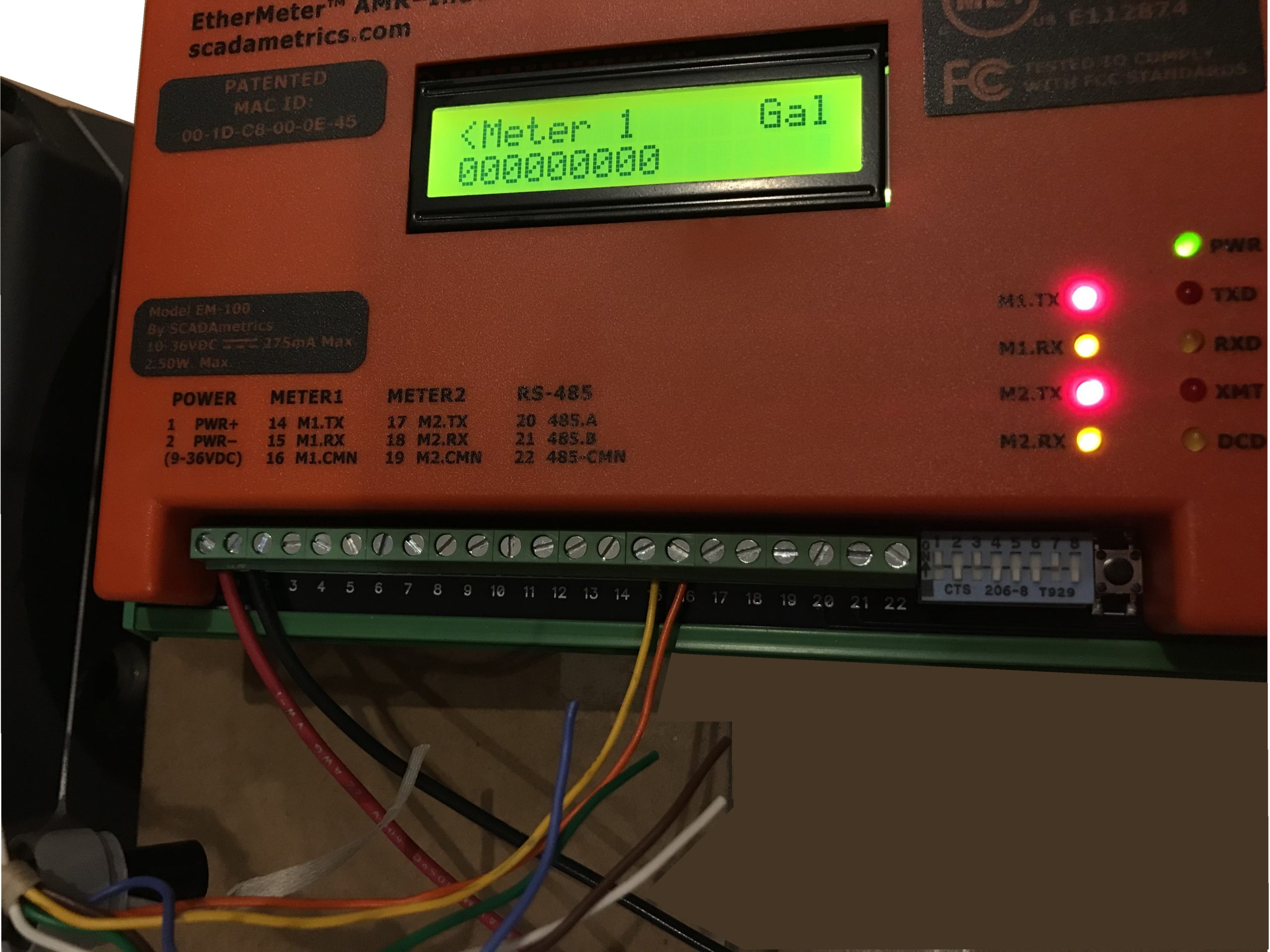
The EtherMeter should also be set up to accept pulses. Note that the EtherMeter’s pulse de-bounce filter should be not be activated (set DB1=0, DB2=0), because high-speed, solid-state pulses do not need to be de-bounced. De-Bounce is only necessary for meters that feature mechanical (reed-relay) pulse signals. In the EtherMeter, the de-bounce filter is turned OFF, by default.
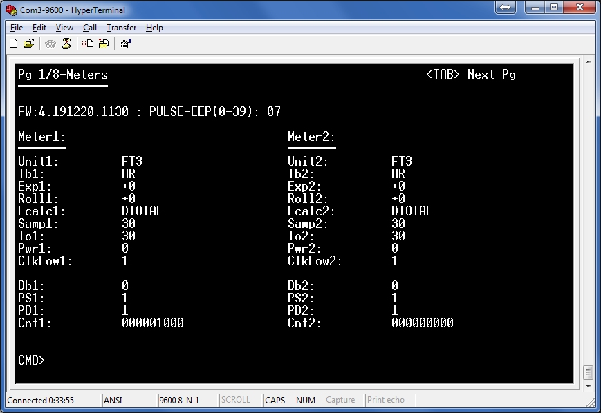
EtherMeter Set Up for Pulses from TCI Gas Meters. 1 Pulse per 1 Cubic Foot. Debounce Filter Disabled.
After the EtherMeter is configured, the gas meter may be brought online to observe correct system operation. If it is not feasible to bring the gas meter online (perhaps no gas devices can be readily turned ON?), then the TCI can be configured to simulate flow pulses. In the “View/Edit” Tab, the User should select the “Pulse Outputs” subheading. Within the “Pulse Outputs” subheading, the User should edit Parameter 005 (Ch-A Pulses Waiting). If the User enters 2000 into the edit box for Parameter 005, then the TCI will be prepared to emit 1000 pulses to the EtherMeter (1000 closed contacts + 1000 open contacts).
After entering 2000 (just an example — another value could be used) into parameter 005, the User must depress the “Write Item” button in the upper right hand corner of the MasterLink window. Also, the simulated pulses will not begin until the User presses the red “Disconnect” button in the lower left hand corner of the MasterLink window.
The following video illustrates 1000 pulses collected by the EtherMeter. Note the blinking of the M1.RX LED (yellow), which turns OFF during each contact “closure” and turns ON during each contact “open”:
Special thanks to Honeywell engineer Greg Carrelli for his expert assistance with the TCI and MasterLink software!… and special thanks to Jason Brown at Heck Inc. for the generous loan of the gas meter, TCI index, and MasterLink software!
Are you interested in how SCADAmetrics technology can help connect your Honeywell TCI-equipped gas flow meters to your SCADA, Telemetry, or Building Automation System? Give us a call! We’ll be glad to discuss the details!